Extended upstream in practice: Towards the high-split
At ANGA COM 2022 I had the pleasure to participate in the panel “DOCSIS 4.0 – Precision Equipment enables Extended Spectrum”. The panel was brilliantly hosted by Anthony Basham, and industry experts including Georg Heiler, Nick Padfield, and Jay Lee shared their latest insights. During and after the panel I received several questions related to my topic and decided to answer them in this article. But to answer them properly, I need to put them into the right context, thus my post merges the key elements of my original speech, the questions, and my answers.
Reasons behind the high-split decision
Today we see many European cable operators moving or planning to move from 65/85 MHz to 204/258 MHz high-split cable networks. Based on our learnings from these transformations, I will next share some insights that may help you once the 65/85 MHz split is not anymore enough and FTTH or fixed wireless competitors are knocking on your customers’ doors. Due to the competition, rising broadband speeds – and network convergence – also distributed access architecture (DAA) rollouts are probably in your agenda. As the DAA rollouts and the split changes require street cabinet visits and careful planning, running both upgrade projects in parallel makes sense.
The target once the rollout is completed
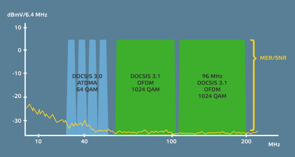
Figure 1 illustrates what is the likely rollout target in one point of the network. It shows the Remote PHY (RPD) or Remote MACPHY (RMD) upstream input channels after your network has been upgraded, new DAA devices are installed, and amplifier diplexers have been changed. (Most operators in Europe have already 204/258 MHz capable network elements in use supporting frequencies up to 1.2 GHz. Therefore, only plug-in diplexers must be changed.) The yellow line describes noise dominated by the low frequency ingress below 25 MHz.
Even after the DOCSIS 3.1 upgrade, you probably still have some DOCSIS 3.0 single-carrier QAM (SC-QAM) channels in your network as legacy modems cannot be changed overnight. Above these SC-QAM channels the first OFDMA block is followed by a full OFDMA block being 96 MHz wide and stopping below 204 MHz. The quality of diplexers and network elements defines how close to 204 MHz you can place the highest OFDMA subcarrier but the promised effectiveness of the OFDMA forward error correction gives some margin at the edges.
Reaching the illustrated target requires a considerable amount of knowledge, planning, and decisions. The target also raises the two important additional questions, which I will answer next: Can you move gradually towards the 204/258 MHz split or do you need to change all network components, especially wall outlets at once and if the gradual change is possible, what should be considered?
Attenuation is not your enemy
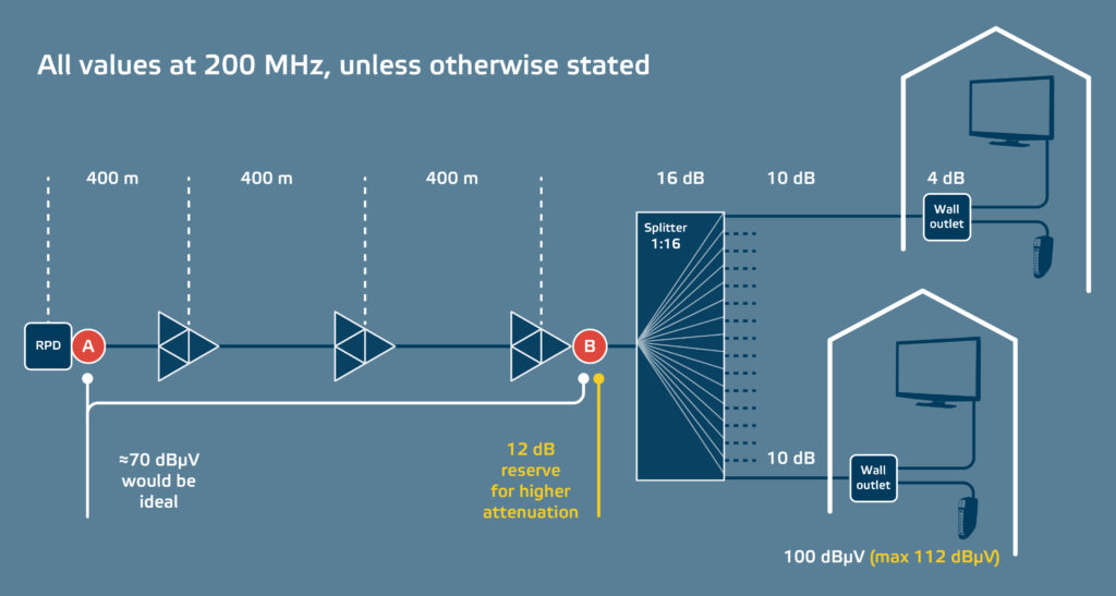
While network attenuation is usually a real concern, this is not the case with upstream frequencies. In fact, the network attenuation of the return path turns out to be beneficial as it increases signal to noise ratio (SNR) which leads to higher modulation error ratio (MER) and enables use of more advanced modulation constellations. This is illustrated in Figure 2.
When amplifier cascade is adjusted correctly, either manually or automatically, the cascade is transparent. Therefore, the signal level at the RPD input (point A) is the same as it is in the amplifier input (point B). The example shows attenuations of a 16-way splitter (≈16 dB), drop cables (each 10 dB), and wall outlets (each 4 dB). These elements could attenuate even more, as a higher attenuation would lead to a higher cable modem output level because cable modems compensate losses of the last drop in accordance with the instructions a cable modem termination system (CMTS) or a converged cable access platform (CCAP) core give to the cable modems. Thus, higher losses improve SNR and MER. In Figure 2, the cable modem has around 12 dB margin (112 dBuV – 100 dBuV) that could be used to compensate even higher losses. However, minimising attenuation of the last drop at higher frequencies is the other side of the coin and high frequency behaviour dominates how the elements behave at lower frequencies.
But would the higher cable modem output level mean higher signal disturbance levels between two neighbouring households? Actually, no. For example, if a cable modem transmit level is 12 dB higher because of the higher attenuation of the drop (22 dB instead of 10 dB), the whole path between two neighbours attenuates 24 dB more as the path includes two drops. In this case we assume that all drops would have equal attenuation and are served by a 16-way splitter. In practice, drop cables do not have equal length and the splitter is a tap. This assumption simplifies the example and is made for illustrative reasons. However, the simplification does not falsify the main point. Even when the length of drop cables varies, the attenuation is not your enemy below 204 MHz. In real life, we have seen operators mainly adding return path attenuators in their networks during the 204/258 MHz upgrades.
Disturbances and leakages
When cable modem transmission levels are increased, also the leakage signal level inside one household increases. Thus, a proper isolation between wall outlet ports becomes paramount. In practice, our recommendation is around 55 dB between television and data ports. This would mean that television or set-top-box (STB) tuners could see the leakage level around 57 dBuV, as Figure 3 demonstrates. But with the leakage below 204 MHz, why would this even matter as the lowest frequency of television channels must be above 258 MHz once networks are upgraded?
Isolation matters because tuners are still sensitive for frequencies below 204 MHz. In practice, the 57 dBuV leakage level can be slightly more than the received television signal level. While the leakage level is high, television and STB tuners are typically not sensitive for “out of band” disturbances that are 54 MHz below the lowest payload frequency. Alas, anecdotal evidence suggests that some tuners are disturbed by these “out of band” signals causing visible artifacts in television picture. If your plan is to have OFDMA upstream, and you can control which STB models your subscribers use, it would be beneficial to test these STB models before the planned OFDMA roll-out.
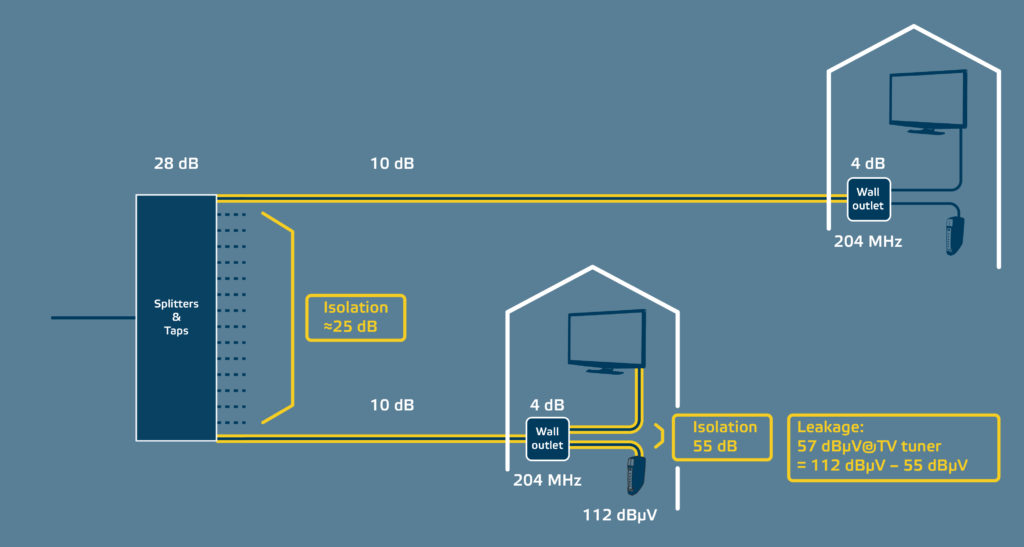
How about the neighbour? The neighbour is safe as the cable modem transmission would first go through a 49 dB (4 dB + 10 dB + 25 dB + 10 dB) attenuation path. In addition, the neighbour’s 204/258 MHz wall outlet will attenuate the transmission in the television port below 204 MHz so much that the leakage level would be far below problematic range. A more important question is, what happens if the neighbour still has a 65/85 MHz wall outlet as Figure 4 shows? In gradual high-split rollouts this would be the case. In that case, the attenuation would be 53 dB (49 dB + 4 dB) and television and STB tuners receive signal at 59 dBuV (112-53). Again, we have a disturbance that should not cause any problems, but our recommendation stays the same; it would be beneficial to test your STB models before the planned OFDMA roll-out.
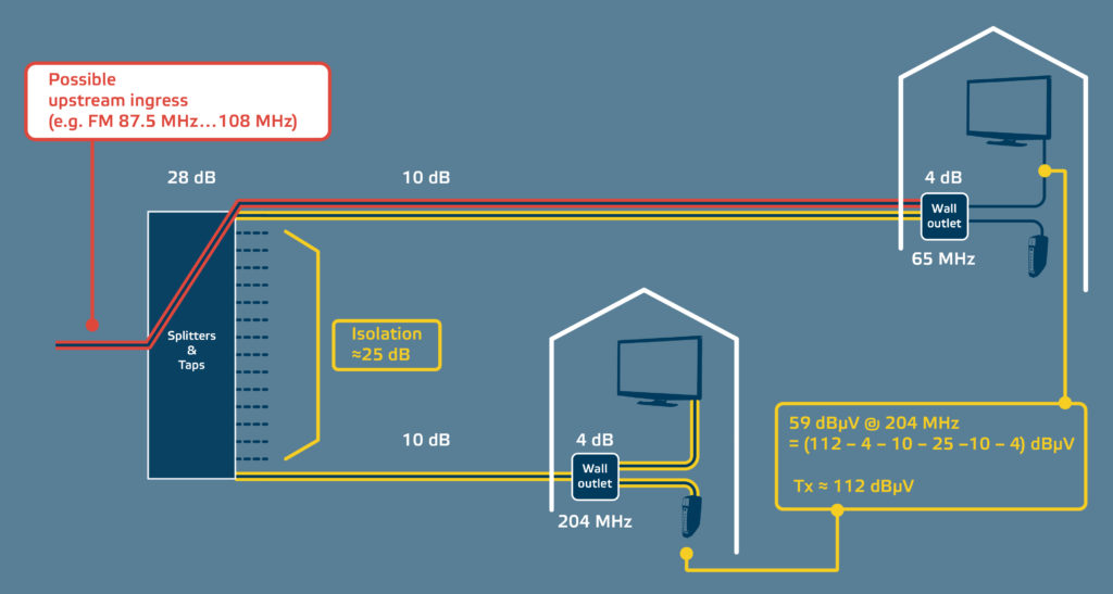
FM ingress and OFDMA
The second problem seen with the 65/85 MHz wall outlet is caused by the FM radio signal. Although the 204 MHz return path means absence of FM radio services provided by the cable operator, the FM frequencies are still in the air and may enter the network via old wall outlets that still have FM ports. These ports are either not connected or connected to FM radios via coaxial patch cables, and sometimes only a patch cable is connected to the wall outlet and an unterminated end lies on the floor like an antenna.
The FM ingress is a real issue that some of our operator customers have seen in their network and one reason why cable operators have hesitated to use the FM band for the lower OFDMA block that Figure 1 illustrates. This may sound counter-intuitive, shouldn’t the OFDMA be excellent against ingress? Shouldn’t the dynamic modulation profile change per subcarrier be exactly what would tackle the ingress issue? Yes, but… Around two years ago, when distributed access rollouts were already ongoing, some early high-split OFDMA adopters were surprised how floppy the OFDMA seemed to be. Indeed, some CCAP cores were not supporting dynamic modulation changes per subcarrier. In 2022, literally speaking, this should not be an issue anymore.
Summary
To recap, what to do with the wall outlets and 204 MHz return path in practice? How can an operator move from 65/85 MHz networks to 204/258 MHz? From a technical perspective, the easiest option would be to change all wall outlets at once and use wall outlets with high port-to-port isolation. In that case, a future-proof alternative would be to select 1.8 GHz capable wall outlets.
The complete network-wide 204/258 MHz upgrade would eliminate leakage issues disturbing tuners and possible FM ingress problems. Unfortunately, this option is expensive and often impractical. Usually, operators have defined a certain limit for the upstream per subscriber, for example 50 Mbit/s, that triggers a new wall outlet installation but only this 50 Mbit/s heavy user gets 204/258 MHz wall outlet(s) while neighbours continue with their 65/85 MHz wall outlets. In that case, the operator may use the higher OFDMA block together with DOCSIS 3.1 modem. The lower OFDMA block is not used if the CCAP core, surprisingly, does not support dynamic modulation profile changes per subcarrier. Once all wall outlets in a network segment have been upgraded, also the lower OFDMA block can be used safely.
It is not easy to write short but still all-inclusive blogs. Please contact me or my colleagues to discuss more!
Arttu Purmonen
Arttu Purmonen
I joined Teleste in 1997 and engineered video processing and data transmission products. I have worked as engineer, project manager, product manager and business director but understanding customer perspective has always motivated me. It brought me to be responsible for system and technical marketing where my internal driving force and former experience can party together. See my LinkedIn.